Advertisement
Quick Links
PREFACE
Thank you for buying Navis anemometer sensor. This manual provides information for the best performance and safe application of the
WS and WSD wind sensors. This manual does not cover the receiver/display unit, for which the manuals will come separately.
Read this manual carefully before starting the installation of the sensors. Keep this manual after installation for future reference.
PRODUCT LAYOUT (exploded view)
4.
1.
3.
2.
5.
Figure 1. WS sensor
BEFORE FIRST USE
For enable sensor power supply remove protective foil from battery contact.
For sensor battery access please look at "BATTERY REPLACEMENT" section.
ASSEMBLY
The sensor is supplied with a battery inserted and is ready for installation.
Before installation insert the cups on sensor. Place the cups on axe and
press the center part with moderate force to end position.
To remove the cups, grab them in the center part and pull from the
axle with moderate force.
WSD sensor - attaching the aluminum rod holder (Figure 3.):
1. Insert the aluminum holder into opening o n sensor (step 1).
2. Insert (step 2) the screw into the assembly hole.
Check and adjust vertical alignment between sensor body
and aluminium tube (step 3).
3. Tighten (step 4) the screw into the assembly hole.
INSTALLATION
WS and WSD sensors to be mounted on 20 mm diameter vertical pool
as shown on Figure 4.
At WSD sensor turn the N mark to Nord.
Calibrating of North is possible also after installation, on display unit.
Mount sensor to highest possible position with unobstructed air flow.
Use self-leveling mounting assembly (optional) if vertical sensor position
can't be ensured with vertical holder (for example at mobile cranes).
For maximum range there should be a clear and unobstructed line of sight
between the sensor and antenna of display/receiver unit.
WIRELESS WIND SPEED / DIRECTION SENSOR
WS 010-2 (wind speed sensor)
WSD 011-2 (wind speed and direction sensor)
1.
3.
2.
6.
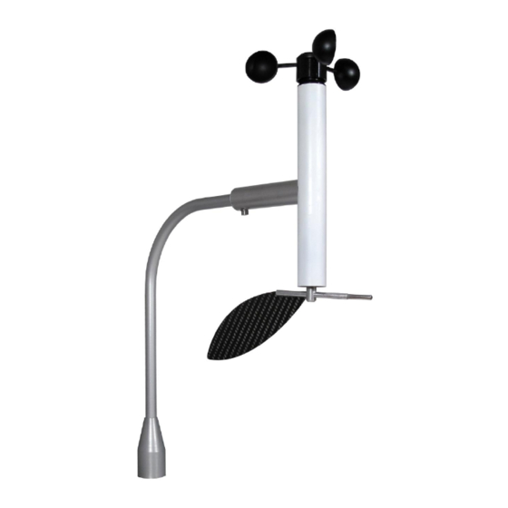
Figure 2. WSD sensor
MANUAL
Models:
4.
7.
8.
5.
1.
Figure 3. WSD sensor assembly
Figure 4. Sensor installation on vertical pool
1.
Wind cups
2.
Wind speed head with bearings
3.
PCB - Electronic driving circuitry
4.
Battery
5.
Sensor main body
6.
Aluminum bottom plug
7.
Wind direction head with bearings
8.
Wind vane
2.
4.
1.
2.
3.
3.
Advertisement

Related Manuals for NAVIS WS 010-2


Summary of Contents for NAVIS WS 010-2
- Page 1 PREFACE Thank you for buying Navis anemometer sensor. This manual provides information for the best performance and safe application of the WS and WSD wind sensors. This manual does not cover the receiver/display unit, for which the manuals will come separately.
- Page 2 OPERATION Sensors continuously measure and transmit data of wind speed, wind direction and air temperature. Data packets are transmitted every two second. Refer to the display/receiver unit manual for instructions on how to connect the sensor and the display unit. SENSOR ADDRESS The sensor address is indicated on the label attached to the sensor and on sensor’s PCB.
- Page 3 (2) this device must accept any interference received, including interference that may cause undesired operation. FCC ID: 2AK8G-NAVIS-WS01 NOTE: This equipment has been tested and found to comply with the limits for a Class B digital device, pursuant to part 15 of the FCC Rules.
- Page 4 WARRANTY (LIMITED) The warranty period of NAVIS products is one year after the date of purchase. During limited warranty period any defective product will be repaired or replaced with comparable product without charges. The claimed product will be repaired or replaced only when returned to the store where it was purchased together with original invoice.