Advertisement
Available languages
Available languages
Quick Links
D D
O O
O O
D D
O O
O O
I I
N N
S S
T T
A A
L L
I I
N N
S S
T T
A A
L L
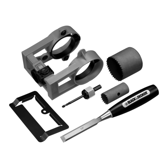
INSTRUCTION MANUAL
Catalog # 79-364, 79-366
2-1/8 in. Wood Hole Saw
INCLUDED IN THIS KIT:
1 in. Wood Hole Saw
Wood Chisel
TOOLS REQUIRED:
3/8 in. or larger
Drill
Hammer
Wood Chisel
REFERENCE
DOOR
THICKNESS
GUIDE:
WARNING: Failure to read and follow all instructions
listed below may result in serious injury or property
damage.
• Read and follow all instructions in drill manual and on hand tools.
• Always use proper eye, respiratory
and hearing protection.
• For use only on wood doors. DO
NOT use on metal doors.
Steps to Install Door
Lock Kit:
• Locate and tighten guide on
1. CLAMP DOOR LOCK GUIDE
door.
• Determine location of door lock
by measuring up from bottom of
R R
L L
O O
C C
K K
R R
L L
O O
C C
K K
L L
A A
T T
I I
O O
N N
K K
I I
T T
L L
A A
T T
I I
O O
N N
K K
I I
T T
Guide
Mandrel
Screwdriver
Tape Measure
BACKSET
LATCH
BORE
door and making a mark on the latch bore side of door.
*Exact measurement depends on door lock, consult door lock
manual.
• Hold guide with black latch face up, closest to you. Using 2
hands, pull open guide. Slide the black latch from right to left until
it clicks. Line up the black cylinder on the latch bore side of door
so your mark is in the middle. Be sure the black cylinder is flush
against the door. Using 2 hands, clamp the guide securely on the
door. NOTE: Clamping the guide will automatically center the latch
bore cylinder.
2. DRILL FACE AND LATCH BORE HOLES
• The guide provides the ability to drill your face bore hole at 2
FACE BORE
different backsets of 2-3/8 in. (60mm) and 2-3/4 in. (70mm)). The
guide is set at 2-3/8 in. (60mm).
*If this is not your preference, pull out the inserts and rotate them
90 degrees and re-insert.
• Assemble the 2-1/8 in. hole saw
by screwing the mandrel into the
hole saw.
• Drill the face bore hole using the
guide as a reference.
Continue drilling until the mandrel
has drilled through to the other side of the door (do not push the
hole saw through to the other side, it could splinter the door).
• Drill hole on other side using the pilot hole as a starting point.
• Disassemble 2-1/8 in. hole saw
LATCH BORE
and assemble 1 in. hole saw.
• Drill hole with 1 in. hole saw
through latch bore guide hole.
Drill hole completely through to face
bore hole.
• Remove guide from door by sliding
black latch to the right and pulling
guide apart.
• Align latch face plate on door edge
and draw outline.
• Chisel out area until face plate sits
flush and drill 3/32 in. (2mm)
diameter pilot holes for screws.
Repeat for strike plate.
3. DOOR HINGE INSTALLATION
If you are replacing a door and the hinge recesses exist on the
LOCATING THE DESIRED DOOR HINGE LOCATIONS
door jam, there are 2 methods of determining where to cut the
recesses out on the door.
• Method #1 - Measure the hinge locations of the previously used
door from the top of the door down (do not measure from the
bottom up since this may create a large gap at the top of the
door).
• Method #2 - Measure the distance from the top of the door jam
down to the first hinge and subtract 1/8 in. This will create a 1/8 in.
clearance gap at the top of the door.
If the door jam that you are installing the door into does not have
hinges or hinge recesses, mark the center of the hinge locations
on the edge of the door. This centering mark will be used in step 2
to locate the Hinge Template.
• Determine which way the door will open and how the hinges will
MAKING DOOR HINGE RECESS
need to be positioned for proper operation. Locate the Hinge
Template on the edge of the door such that the hole lines up with
FACE
BORE
the mark scribed in step one (the center of the hinge).
Installation tip: With a pencil,
outline the inside of the Hinge
Template, this is the area that will
be chiseled out. Remove the
template and position the hinge
inside the pencil lines to verify the
door will open as desired.
• With the Hinge Template in
place, insert a screw into the
hole, and fasten the template
onto the door. With the template fastened to the door, use a chisel
to remove the material inside the template as shown. Remove the
template and chisel out material left behind at the template screw
location. Screw the hinges onto the door.
• Follow instructions provided with door lock for lock set
4. INSTALL DOOR LOCK
installation.
Advertisement

Related Manuals for Black & Decker 79-364


Summary of Contents for Black & Decker 79-364
- Page 1 *If this is not your preference, pull out the inserts and rotate them 90 degrees and re-insert. • Assemble the 2-1/8 in. hole saw by screwing the mandrel into the Catalog # 79-364, 79-366 hole saw. • Drill the face bore hole using the 2-1/8 in. Wood Hole Saw INCLUDED IN THIS KIT: guide as a reference.
- Page 2 (2 3/4 po); son réglage initial est à 60 mm (2 3/8 po). *Si une distance autre que celles indiquées ci-dessus est N° de catalogue 79-364, 79-366 préférable, retirer les pièces et les Scie-cloche à bois de 54 faire tourner sur 90 degrés, puis LA TROUSSE CONTIENT : les insérer de nouveau.
- Page 3 MANUAL DE INSTRUCCIONES perforadora de 2-1/8 pulg. atornillando el mandril a la sierra perforadora. Catálogo N° # 79-364, • Taladre el hueco del diámetro del frente usando la guía como 79-366 referencia. Continúe taladrando hasta que el mandril haya taladrado hasta el otro lado de la puerta (no empuje la broca de...