Advertisement
Quick Links
Ampli er uilt-in Leak Detection Sensor
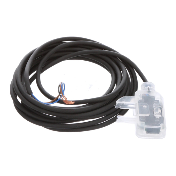
EX-F70 Series
1
SPECIFICATIONS
Type
2m cable length type
Model NPN output
Item No. PNP output
Sensing object
Supply voltage
Current consumption
<NPN output type>
NPN open-collector transistor
Maximum sink current: 50mA
Output
Applied voltage: 30V DC or less (between output and 0V)
Residual voltage: 1.0V or less (at 50mA sink current)
Output operation
ON when normal operation, OFF when leak is detected or the sensor is mounted improperly.
Short-circuit protection
Response time
Abnormal indicator
Normal indicator
Protection
Ambient temperature
Ambient humidity
Ambient illuminance
Emitting element
Material
0.1mm
Cable
cabtyre cable, 2m long
Weight
Accessories
Notes: 1) Highly viscous liquid may not be stably detected.
2) Fluorinert
is the worldwide trademark of 3M.
TM
3) Liquid being detected should be also kept within the rated ambient temperature range.
2
CAUTIONS
This product has been developed / produced for
industrial use only.
Av oid using the produ ct in a n ex plo sive
atmosphere because this product does not have
an explosive-proof protective construction.
Make sure that the power supply is off while wiring.
Take care that wrong wiring will damage the sensor.
Verify that the supply voltage variation is within
the rating.
Take care that if a voltage exceeding the rated
range is applied, or if an AC power supply is directly
connected, the sensor may get burnt or damaged.
If power is supplied from a commercial switching
regulator, ensure that the frame ground (F.G.)
terminal of the power supply is connected to an
actual ground.
Ramco National
INSTRUCTION
MANUAL
MJEC-EXF71 No.0044-45V
SUS mounting bracket type
5m cable length type
EX-F71
EX-F71-C5
EX-F71-PN
EX-F71-PN-C5
Water, Fluorinert
12 to 24V DC ± 10% Ripple P-P 10% or less
10mA or less (PNP output type: 15mA or less)
0.4V or less (at 16mA sink current)
Red LED (lights up when leak is detected or the sensor is mounted improperly.)
Green LED (lights up when the sensor is mounted properly.)
–10 to +60°C (No dew condensation or icing allowed) (Note 3), Storage: –20 to +70°C
35 to 85% RH, Storage: 35 to 85% RH
Incandescent light: 1,000 x or less at the light-receiving face
2
2
3-core PVC
0.1mm
3-core PVC
cabtyre cable, 5m long
Approx. 25g
Approx. 55g
SUS mounting bracket: 1 pc.
800-280-6933 | nsales@ramcoi.com
Thank you very much for purchasing Panasonic products.
Please read this Instruction Manual carefully and thor-
oughly for the correct and optimum use of this product.
Kindly keep this manual in a convenient place for quick reference.
Never use this product as a sensing device for
personnel protection.
In case of using sensing devices for personnel protec-
tion, use products which meet laws and standards, such
as OSHA, ANSI or IEC etc., for personnel protection ap-
plicable in each region or country.
PVC mounting bracket type
2m cable length type
EX-F72
EX-F72-PN
(Note 1) (Note 2)
TM
<PNP output type>
PNP open-collector transistor
Maximum source current: 50mA
Applied voltage: 30V DC or less (between output and +V)
Residual voltage: 1.0V or less (at 50mA source current)
Incorporated
50ms or less
IP67 (IEC)
Infrared LED (non-modulated)
Enclosure: Polypropylene
2
0.1mm
3-core PVC
cabtyre cable, 2m long
Approx. 25g
PVC mounting bracket: 1 pc. each for two-point- xing and adhesive- xing
Do not use during the initial transient time (approx.
50m sec. ) after the power supply is switched on.
In case noise generating equipment (switching
regulator, inverter motor, etc.) is used in the vicin-
ity of this product, connect the frame ground (F.G.)
terminal of the equipment to an actual ground.
Cable extension is possible up to total 50m with
2
0.3mm
, or more, cable. However, in order to re-
duce noise, make the wiring as short as possible.
Do not run the wires together with high-voltage lines
or power lines or put them in the same raceway.
This can cause malfunction due to induction.
In case a surge is generated in the used power sup-
ply, connect a surge absorber to the supply and ab-
sorb the surge.
e sure to use the exclusive mounting bracket when installing
the sensor to avoid human error, etc. Reliable detection can-
not be guaranteed when this mounting bracket is not used.
5m cable length type
EX-F72-C5
EX-F72-PN-C5
0.4V or less (at 16mA source current)
2
0.1mm
3-core PVC
cabtyre cable, 5m long
Approx. 55g
www.panasonicsensors.com
Take c
EX-F7
mistak
Make
DC po
windin
power
In cas
take c
stabiliz
When
wipe
bracke
If there
surfac
operat
Since
LED,
Do no
extran
Avoid
produc
Take
contac
as, thi
In cas
charg
should
3
MO
Insert
welde
hole o
an M4
The tig
Insert
on the
the tw
with M
The tig
Advertisement

Summary of Contents for Panasonic EX-F70 Series
- Page 1 Take c Thank you very much for purchasing Panasonic products. INSTRUCTION EX-F7 Please read this Instruction Manual carefully and thor- MANUAL mistak oughly for the correct and optimum use of this product. Make Kindly keep this manual in a convenient place for quick reference.
- Page 2 2431-1 Ushiyama-cho, Kasugai-shi, Aichi, 486-0901, Japan Phone: +81-568-33-7861 FAX: +81-568-33-8591 stalling About our sale network, please visit our website. M4 stud-bolts on can- (straight type) © Panasonic Industrial Devices SUNX Co., Ltd. 2014 PRINTED IN JAPAN sed. Ramco National 800-280-6933 | nsales@ramcoi.com www.panasonicsensors.com...


