Advertisement
Available languages
Available languages
Quick Links
English
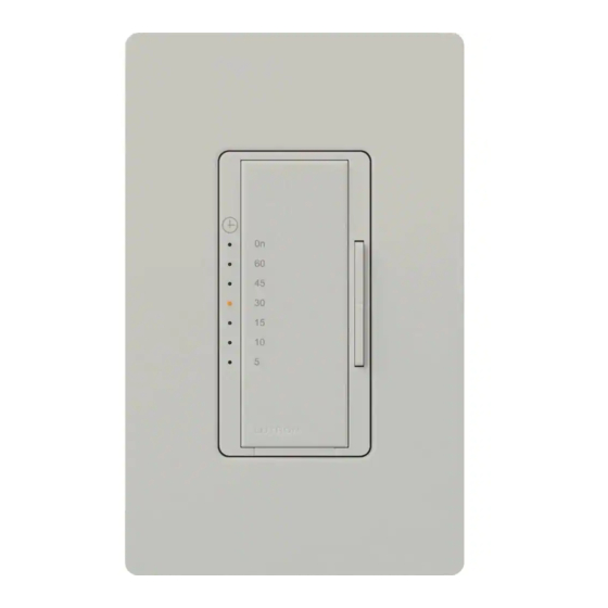
Countdown Timer
MA-T51MN 120 V~ 60 Hz
600 W Lighting or 3 A Fan
Accessory Switch
MA-AS, MSC-AS 8.3 A 120 V~ 60 Hz
The Countdown Timer (MA-T51MN) is rated for lighting and fan loads only.
Important Notes
Please read before installing.
1. Caution: To avoid overheating and possible damage to other equipment, do not use to con-
trol receptacles, or motor-operated or transformer-supplied appliances.
2. Install in accordance with all national and local electrical codes.
3. When no "grounding means" exist within the wallbox then the NEC
2005, Article 404-9
®
allows a wall control without a grounding connection to be installed as a replacement, as
long as a plastic, noncombustible wallplate is used. For this type of installation, cap or
remove the green ground wire on the timer and use an appropriate wallplate such as
Lutron's Claro
or Satin Colors
series wallplates.
®
TM
4. Maestro
Countdown Timers are not compatible with standard 3-way/4-way switches, for
®
use only with Accessory Switches (MA-AS, MSC-AS).
5. Accessory Switches (MA-AS, MSC-AS) can not be used individually and must be used in
conjunction with a Maestro Timer in a 3-way/4-way application.
6. In any 3-way/4-way circuit use only one Timer with up to 9 Accessory Switches (MA-AS,
MSC-AS).
7. Do not use where total lamp wattage is less than 5 W/VA or greater than wattage indicated
on unit label.
8. Operate between 32 °F (0 °C) and 104 °F (40 °C).
9. Protect control from dust and dirt when painting or spackling.
10. Timer may feel warm to the touch during normal operation.
11. Recommended wallbox depth is 2.5 in (64 mm) minimum.
12. Maximum wire length between the Timer and the farthest Accessory Switch (MA-AS,
MSC-AS) is 250 ft (76 m).
13. For safety reasons, do not use Timer to control fixtures that are the only source of illumina-
tion for an area.
14. When controlling a combined fan and light load, the total may not exceed 3 A.
15. Clean Timers with a soft damp cloth only . Do not use any chemical cleaners.
Multigang Installations
When installing more than one control in the same wallbox, it may be necessary to remove all
inner side sections prior to wiring (see below). Using pliers, bend side sections up and down until
they break off. Repeat for each side section to be removed. Removal of Timer side sections
reduces maximum load capacity. Refer to chart below for maximum Timer capacity.
Do not remove
outside
sections.
Breaking Side
Sections
Each control has
Middle control has
inside section
two side sections
removed.
removed.
Derating Chart
Maximum Load
No Sides
1 Side
Load Type
Removed
Removed
Incandescent/
600 W
500 W
120 V Halogen
Magnetic Low Voltage
600 VA / 450 W
500 VA / 400 W
400 VA / 300 W
Electronic Low Voltage
600 W
500 W
Fluorescent
5 A
4 A
General Purpose Fan
3 A
3 A
*Note: The maximum lamp wattage is determined by the efficiency of the transformer, with 70–85%
as typical. For actual transformer efficiency, contact either the fixture or transformer manufacturer.
The total VA rating of the transformer(s) shall not exceed the VA rating of the timer.
Technical Assistance
If you have questions concerning the installation or operation of this product, call the
Lutron Technical Support Center . Please provide exact model number when calling.
U.S.A. and Canada (24 hrs/7days)
Fax +1-610-282-6311
1-800-523-9466
Other countries 8am – 8pm ET
http://www.lutron.com
+1-610-282-3800
Limited Warranty
(Valid only in U.S.A., Canada, Puerto Rico, and the Caribbean.)
Lutron will, at its option, repair or replace any unit that is defective in materials or manufacture within one year after purchase.
For warranty service, return unit to place of purchase or mail to Lutron at 7200 Suter Rd., Coopersburg, PA 18036-1299,
postage pre-paid.
THIS WARRANTY IS IN LIEU OF ALL OTHER EXPRESS WARRANTIES, AND THE IMPLIED WARRANTY OF MERCHANTABILITY
IS LIMITED TO ONE YEAR FROM PURCHASE. THIS WARRANTY DOES NOT COVER THE COST OF INSTALLATION, REMOVAL
OR REINSTALLATION, OR DAMAGE RESULTING FROM MISUSE, ABUSE, OR DAMAGE FROM IMPROPER WIRING OR INSTAL-
LATION. THIS WARRANTY DOES NOT COVER INCIDENTAL OR CONSEQUENTIAL DAMAGES. LUTRON'S LIABILITY ON ANY
CLAIM FOR DAMAGES ARISING OUT OF OR IN CONNECTION WITH THE MANUFACTURE, SALE, INSTALLATION, DELIVERY,
OR USE OF THE UNIT SHALL NEVER EXCEED THE PURCHASE PRICE OF THE UNIT.
This warranty gives you specific legal rights, and you may have other rights which vary from state to state. Some states do not
allow the exclusion or limitation of incidental or consequential damages, or limitation on how long an implied warranty may last,
so the above limitations may not apply to you.
This product is covered under one or more of the following U.S. patents: 4,835,343; 5,017,837; DES 353,798 and correspon-
ding foreign patents. U.S. and foreign patents pending. Lutron, Claro, and Maestro are registered trademarks and FASS and
Satin Colors are trademarks of Lutron Electronics Co., Inc. NEC is a registered trademark of the National Fire Protection
Association, Quincy, Massachusetts. © 2007 Lutron Electronics Co., Inc.
Lutron Electronics Co., Inc.
7200 Suter Road
Coopersburg, PA 18036-1299, U.S.A.
Made and printed in the U.S.A. 2/07 P/N 030-929 Rev. A
Lutron Technical Support Center
Installation
1 1
Turning OFF power.
• Turn power OFF at circuit breaker (or remove fuse).
2 2
Removing wallplates and switches.
• Remove the wallplate and switch mounting screws.
• Carefully remove switch from wall (do not remove wires).
Danger: Verify power to each switch
is OFF before proceeding.
3 3
Identifying the circuit type.
3a - Single-Location control
One switch controlling a light fixture.
This switch will be a single-pole. The switch will
have insulated wires connected to two screws of
the same color plus a green ground screw.
If a neutral wire is not present, contact
a licensed electrician for installation.
Ground
(Bare Copper or
Green Wire)
3b - Two-Location control
Two switches controlling a light fixture.
Both switches will be 3-way. Each switch will
have insulated wires connected to three screws
plus a green ground screw. One of these wires is
connected to a screw of a different color (not
green) or labeled COMMON. TAG this wire on
both switches to identify when wiring.
Ground
Tagged wire
(Bare Copper or
If a neutral wire is not present in the box that
Green Wire)
is last in the circuit before the load, contact a
Different colored
licensed electrician for installation.
screw (Common)
3c - Three-Location control
Three switches controlling a light fixture.
Note: Screw
Two switches will be 3-way and one will be a
placement may
4-way. Tag the two 3-way switches as in the
be different on
Two-Location diagram above. The 4-way switch
your switch.
will have insulated wires connected to four
screws plus a green ground screw. TAG the two
Same colored
same color insulated wires which are connected
screw (or
to opposite colored screws.
marked IN or
Ground
Tagged wires
OUT)
(Bare Copper or
If a neutral wire is not present in the box that
Green Wire)
is last in the circuit before the load, contact a
2 Sides
licensed electrician for installation.
Removed
4 4
Disconnecting switch wires.
400 W
Important Note: Your wall switch may have two wires attached to the same screw (see illustra-
tions below for examples). Tape these two wires together before disconnecting. When wiring,
connect wires to the Timer the same way they were connected to the switch.
400 W
One wire in the
push-in terminal
and one to the
screw.
3 A
Screw
Push-in
Terminals:
Terminals:
3 A
Turn screws to
Insert screw-
loosen.
driver. Pull
wire out.
Important Wiring Information
When making wire connections, follow the recommended strip lengths and combinations for the
supplied wire connector. Note: All wire connectors provided are suitable for copper wire only.
For aluminum wire, consult an electrician.
Trim or strip wallbox wires to the length indicated
by the strip gauge on the back of the timer.
Push-in Terminals: Insert wires fully.
NOTE: Push-in terminals are for use with #14 AWG solid
copper wire only. DO NOT use stranded or twisted wire.
OR
Screw Terminals: Tighten securely.
Screw terminals are for use with #12 or #14 AWG solid
copper wire only. DO NOT use stranded or twisted wire.
Wire Connector:
Twist wire
Use to join one 14 AWG or 12 AWG ground
connector
wire with one 18 AWG timer ground wire.
tight.
1-800-523-9466
24 hrs / 7 days
5 5
Wiring.
• For installations involving more than one control in a wallbox, refer to Multigang
Installations before beginning.
• Use the screw or push-in terminals when making connections on the Timer or
Accessory Switch.
• If push-in terminals are used, tighten screws securely.
For new construction
• Wire all controls before mounting.
go to step 5.
Single-Location control
Silver screw
Brass screw
Timer
Black screw
Ground
Green wire
Reference Wiring Diagram
Countdown Timer
Brass
Blue
Live
Silver
Black
120 V~
Green
Light or
60 Hz
Fan
Fixture(s)
Ground
Neutral
Neutral
Wallbox
Multi-Location control
Timer must be installed on the load side of multi-location wiring.
For Two-Location Control wiring, follow Sections A & B below. One location will be replaced
with a Countdown Timer and the other with an Accessory Switch.
A
B
Line side
Accessory Switch
Brass
Blue
Live
Black
120 V~
Green
60 Hz
Ground
Neutral
Wallbox
Wallbox
Accessory
For Three-Location Control (or more) wiring, follow Sections A, B & C. One location will be
Switch
replaced with an Countdown Timer and the others with Accessory Switches. Only one
Countdown Timer can be used with up to 9 Accessory Switches.
A
C
Line side
Accessory Switch
Brass
Blue
Live
Black
120 V~
Green
60 Hz
Ground
Neutral
Wallbox
Wallbox
One continuous
wire to the
screw.
Section A: Line side
Brass screw
Blue screw
Looped Wire:
Turn screw to
loosen.
Accessory
Switch
Tag
Black screw
Ground
Green wire
Section B: Load side
Timer or
Accessory
Switch
Brass screw
Blue screw
Tag
Countdown
Timer
Black screw
Ground
Silver screw
Green wire
www.lutron.com
Section C: 4-Way
Brass screw
Accessory
Switch
Black screw
Wiring the Countdown Timer:
Green wire
• Connect the green ground wire on the Timer to
the bare copper or green ground wire in the wall-
box. (See Important Note 4.)
• Connect the neutral wire in the wallbox to the sil-
ver screw terminal on the Timer. If a neutral wire
is not available in the wallbox, contact a licensed
electrician for installation.
• Connect the live wire (the wire leading to the cir-
6 6
cuit breaker or fusebox) removed from the switch
Mounting Control(s) to wallbox.
to the black screw terminal on the Timer.
• Form wires carefully into wallbox, mount and align the control(s).
• Connect the remaining wire removed from the
• Install the wallplate(s).
switch to the brass screw terminal on the Timer.
• Tighten the blue screw terminal on the Timer. It is
not used in a single-pole circuit.
Start screws.
If the wires connected to the black and
brass screws are reversed, the unit will
not operate. It may be necessary to swap
the connections to ensure that the brass
screw is connected to the load.
7 7
Turning ON power.
• Turn power ON at circuit breaker (or replace fuse).
Operation
Tap Button Options
• Tap once when unit is off -
Controlled load turns ON and
Load side
countdown timer begins.
When time expires, load
Countdown Timer
turns OFF.
• Tap once when unit is on -
Brass
Blue
Controlled load turns OFF
Silver
and countdown timer resets.
Black
Green
• Tap twice quickly -
Light or
Fan
Controlled load turns on
Fixture(s)
Ground
without a time limit.
Neutral
One Minute Indication:
B
4-Way
Load side
When only one minute of time is remaining, the load will briefly
turn off and on to give an indication the timer is about to turn off.
Accessory Switch
Countdown Timer
IMPORTANT NOTICE:
Brass
Blue
Brass
Blue
To replace bulb, power may be conveniently removed by pulling the FASS
Silver
switch out on both the Timer and any Accessory Switches.
Black
Black
Green
Green
Light or
For any procedure other than routine bulb replacement, power must
Fan
Fixture(s)
Ground
Ground
be disconnected at the main electrical panel.
Neutral
To learn about the Advanced Features of Maestro Wall Controls including
Wallbox
locked preset and timer bypass disable, please visit:
www.lutron.com/maestro/advfeatures
or call the Lutron Technical Support Center.
Wiring the Accessory Switch on Line side:
• Connect the green ground wire on the Accessory
Switch to the bare copper or green ground wire
in the wallbox. (See Important Note 4.)
• Connect the tagged wire removed from the switch to
the black screw terminal on the Accessory Switch.
• Connect one of the remaining wires removed from the
switch to the brass screw terminal on the Accessory
Switch.
• Connect the remaining wire removed from the switch
(note wire color) to the blue screw terminal on the
Accessory Switch.
Wiring the Timer on Load side:
Troubleshooting
• Connect the green ground wire on the Countdown
Timer to the bare copper or green ground wire in
Symptom
the wallbox. (See Important Note 4.)
Load does not turn ON, but
• Connect the neutral wire in the wallbox to the sil-
LED on Timer is ON.
ver screw terminal on the Countdown Timer.
• Connect the tagged wire removed from the switch to
the brass screw terminal on the Countdown Timer.
• Identify the color of the wire that was connected to
the blue screw terminal in Section A. Connect the
Load does not turn ON and
same color wire to the blue screw terminal on the
LED on Timer is OFF.
Countdown Timer.
• Connect the remaining wire removed from the switch
to the black screw terminal on the Timer.
Load turns ON and Timer
works, but Accessory Switch
does not work.
Load does not remain ON,
LED glows dimly or blinks.
Replace the 4-way switch(es):
Note: 4-way switches must be replaced with an
Tag
Blue
Accessory Switch.
screw
• Connect the green ground wire on the Accessory
Switch to the bare copper or green ground wire
in the wallbox. (See Important Note 4.)
• Identify the color of the wires that were connected to
the blue screw terminals in Sections A & B. Connect
both of the same color wires to the blue screw termi-
nal on the Accessory Switch (one wire to the screw
Ground
and the other to the push-in terminal.
• Connect one of the remaining wires removed from the
switch to the black screw terminal on the Accessory
Switch.
• Connect the remaining wire removed from the switch
to the brass screw terminal on the Accessory Switch.
Caution: Do not overtighten mounting screws.
Align control and
tighten screws.
Snap on Claro
wallplate.
Press to increase time
Press to reduce time
LEDs
• Orange LEDs indicate timer duration
or remaining time in minutes
• Top green LED labeled ON has no
time limit
• Bottom LED blinks rapidly to indi-
cate 1 minute of time remaining
LEDs
(not available on Accessory Switch)
FASS
- Front Accessible
TM
Service Switch
• Easy-to-follow
Instructions
• Instrucciones
Fáciles de Seguir
030-929
Possible Cause
•Light bulbs are burned out.
•Timer is not properly wired.
•Neutral wire is not connected.
•Load not properly installed.
•Fan not turned on at fixture.
•Timer is not properly wired, wires connected to brass and
black screw terminals may be reversed.
•Neutral wire is not connected
•Front Accessible Service Switch ( FASS ) on Timer or any
Accessory Switch is pulled out to the OFF position.
•Breaker is OFF or tripped.
•Wire connected to the blue screw terminal on Timer is not
the same wire connected to the blue screw terminal on
Accessory Switch.
•Timer is not installed on the load side of the circuit.
•Blue screw terminal miswired to neutral wire or touching
ground.
Advertisement

Summary of Contents for Maestro MA-T51MN
-
Page 1: Troubleshooting
Accessory Switch. ding foreign patents. U.S. and foreign patents pending. Lutron, Claro, and Maestro are registered trademarks and FASS and Satin Colors are trademarks of Lutron Electronics Co., Inc. NEC is a registered trademark of the National Fire Protection •Timer is not installed on the load side of the circuit. - Page 2 Sección A. Conecte el cable del spondientes patentes extranjeras. Patentes de EE.UU. y extranjeras pendientes. Lutron, Claro, y Maestro son marcas registradas, temporizador. y FASS y Satin Colors son marcas registradas de Lutron Electronics Co., Inc. NEC es una marca registrada de National Fire mismo color al tornillo azul del Temporizador de •El borne del tornillo azul no está...